
Views: 0 Author: Site Editor Publish Time: 2026-09-30 Origin: Site
Pneumatic unloading acts as the primary operational bottleneck for dry bulk fleets everywhere. Success relies entirely on fluid dynamics, not just total tank volume. Fleet managers often struggle when they balance air volume (CFM) and pressure (PSI) against physical pipeline constraints at delivery sites. This mismatch frequently causes clogged pipes, wasted fuel, and massive operational delays. Solving this issue matters heavily because profitability in bulk transport depends on rapid, predictable turnaround times. Specifying an efficient cement tanker unloading system requires aligning compressor output directly with piping geometry. This alignment minimizes friction loss, reduces fuel burn, and prevents severe material compaction inside the lines. In this guide, you will learn how to accurately evaluate compressor capacity for your fleet. We will explore the core physics behind pipeline design to keep cement flowing optimally. Finally, you will discover actionable strategies for mitigating risks and troubleshooting common system blockages on the job site.
Oversized compressors do not guarantee faster unloading; they often cause filter blowouts and cement compaction if pipeline diameter cannot handle the air volume.
Pipeline geometry—specifically the number of bends and pipe diameter—dictates the required friction loss calculations for the system.
Optimal unloading requires standardizing Standard Operating Procedures (SOPs) so operators maintain the specific "sweet spot" pressure (typically 12-15 PSI for standard Portland cement).
Evaluating a **Bulk Cement Tanker** purchase must include a localized audit of the receiving silo's pipe network, not just the trailer's specs.
Poorly matched pneumatic systems create massive hidden costs for logistics operations. Managing a Bulk Cement Tanker requires precise harmony between the truck and the receiving silo. When components clash, delivery turnaround times plummet. An optimized setup must achieve steady, predictable flow rates consistently. You should expect an output of 1 to 1.5 tons per minute under normal site conditions. Efficient operations also leave less than 1% residual material inside the tank after completion. Hitting these success criteria keeps your fleet moving and highly profitable.
Failing to optimize these systems introduces severe operational risks across your business. You must watch out for these primary dangers:
Demurrage: Excessive unloading times directly lead to costly site penalties. Construction sites run on strict schedules. You lose money every single minute the truck sits idle blocking the intake zone.
Equipment Wear: Pushing against abnormally high pressure increases fuel consumption rapidly. It also accelerates mechanical wear on the Power Take-Off (PTO) and the compressor bearings.
Product Degradation: Over-aeration actively ruins the cement load. It frequently causes dust collector failures at the receiving silo, which creates massive environmental hazards and site shutdowns.
Airflow and air pressure play different but equally vital roles during material transfer. CFM (Cubic Feet per Minute) acts as the carrier vehicle for the material. PSI (Pounds per Square Inch) provides the sheer muscle needed to overcome pipeline resistance. Many operators unfortunately fall for the "more is better" fallacy regarding capacity. They assume a higher-capacity compressor automatically yields faster discharge times. This assumption proves dangerously incorrect in practice. Excessive CFM entering a restricted pipe creates violent turbulent flow. The air moves much too fast, which disrupts the delicate cement suspension. This turbulence leads directly to hard line blockages and blown silo filters.
You must evaluate your compressor systems across specific technical dimensions. First, consider the internal fluidization limits. The compressor must perfectly match the permeability of the fluidization pads inside the tank. Too much air blinds the pads and causes channeling. Too little air fails to lift the heavy cement off the bottom. Next, you must compare compressor architectures. Rotary vane models offer continuous, stable airflow. Screw compressors excel at delivering peak pressure capabilities for challenging vertical lifts.
Industry baselines provide a reliable standard for procurement teams. For a standard 4-inch discharge line, engineers target 350 to 500 CFM. This specific range perfectly balances required suspension velocity against systemic pressure limits.
Compressor Type Comparison Chart
Compressor Architecture | Airflow Stability | Pressure Capability | Ideal Application Scenario |
|---|---|---|---|
Rotary Vane | Highly continuous, low pulsation | Moderate (Peaks up to 15 PSI) | Standard silo deliveries, short horizontal runs |
Screw Type | Pulsating but highly robust | High (Easily maintains 15-20+ PSI) | Extremely tall silos, complex pipeline geometries |
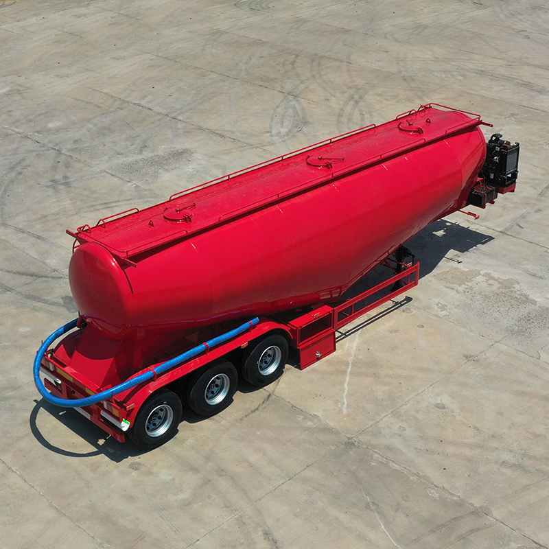
Successful pneumatic transfer relies heavily on strict core physics. Cement must maintain a minimum conveying velocity to stay suspended inside the air stream. If velocity drops below this threshold, particles fall out of suspension immediately. They settle at the bottom of the pipe and rapidly form an impenetrable plug. You must account for friction loss at every physical step of the delivery path.
Pipeline geometry factors dictate your systemic limits entirely. You must pay close attention to these three elements:
Diameter: Pipe size dictates internal air velocity requirements. Moving from a 4-inch pipe to a 5-inch pipe changes the cross-sectional area drastically. Larger pipes require exponentially more air volume to maintain suspension. If you use a 5-inch pipe but keep CFM constant, velocity drops and causes instant blockages.
Length & Vertical Lift: Physical distance steals kinetic energy. You must calculate the exact pressure drop per 100 feet of horizontal run. Vertical silo climbs require significantly more pressure to fight gravity and lift the dense product.
Elbows and Bends: A Cement Tanker Trailer delivery system faces immense friction at every turn. You must use long-radius sweep elbows instead of hard 90-degree fittings. Sharp corners cause severe impact wear and restrict airflow drastically.
Matching the trailer equipment to the delivery environment determines your overall success. You cannot treat the truck and the receiving silo as isolated units. They operate together as one interconnected mechanism. An efficient delivery requires matching the source generation perfectly to the destination constraints.
Engineers use a specific sizing formula to ensure proper equipment compatibility. The required airflow equals the pipeline cross-sectional area multiplied by the minimum conveying velocity. You then add a leakage factor to account for minor seal losses. This exact math prevents you from overpowering the silo or underpowering the flow.
Use this shortlisting logic when designing your pneumatic setup:
Prioritize screw compressors if primary delivery routes involve tall silos or long horizontal runs. They maintain high efficiency at elevated pressures above 15 PSI.
Prioritize rotary vane setups if you deliver to standard, close-proximity batch plants. High-CFM, low-pressure configurations maximize discharge speed in these controlled environments.
You must acknowledge one critical variable regarding these physical calculations. These formulas assume you are moving dry, highly aeratable Portland cement. Blended cements or ground slag behave completely differently. They alter internal fluidization dynamics due to varied bulk densities. You will need to recalibrate your pressure and airflow expectations whenever you handle these heavier materials.
The best-designed system fails instantly if operators execute the wrong sequence. Strict Standard Operating Procedures (SOPs) protect your expensive equipment. Operators must pressurize the tank fully before they open the discharge valve. Opening valves too early floods the empty pipeline with dense, un-aerated cement. This mistake causes an immediate, severe plug.
Routine maintenance demands your daily attention to prevent catastrophic failures. You must execute regular inspections of all non-return valves. This simple step prevents cement backflow from entering and destroying the compressor housing. You also need to monitor the physical condition of the aeration fabrics inside the tank. Canvas or synthetic pads dictate exactly how well the compressor air is utilized. Worn or wet pads create dead zones where cement absolutely refuses to fluidize.
Blockages still happen despite the best preparation. When they do occur, operators need safe, standard practices for clearing plugged lines. Never hammer violently on the exterior pipes. Instead, slowly bleed off the entire system pressure first. Use designated cleanout ports to safely vacuum out the blockage. This methodical approach prevents severe damage to the pipeline infrastructure and guarantees operator safety.
Unloading speed acts as a product of systemic balance rather than isolated component power. When you optimize the entire pneumatic flow, you reduce site delays and protect your equipment from premature failure. You can improve your daily operations by following a few clear steps. First, audit your most restrictive delivery sites before purchasing new equipment. Next, measure the exact pipe diameters and vertical climbs at those specific locations. Spec your compressor sizing and hose dimensions backward based on those site constraints. Finally, train all operators on strict start-up and shutdown sequences to eliminate human error.
A: The ideal pressure typically ranges between 12 and 14 PSI. However, this target heavily depends on the silo height and total line length. Maintaining this specific range ensures smooth fluidization without overworking the compressor. Exceeding 15 PSI frequently indicates a downstream blockage or severely restricted airflow. Operators should always monitor gauges closely and bleed pressure if it spikes unexpectedly.
A: Pipe diameter changes everything due to the square-cube law in fluid dynamics. Moving from a standard 4-inch pipe to a 5-inch pipe increases the cross-sectional area by over 50%. You need significantly more CFM to fill that extra space. If CFM remains unchanged, the air velocity drops immediately. This drops the cement out of the air stream and plugs the line.
A: Yes, absolutely. Every receiving silo features a dust collector designed to vent a specific volume of air. If your compressor pushes more air than the silo can vent, pressure builds rapidly inside the structure. This excess volume can easily cause violent filter blowouts, damage environmental seals, or lead to dangerous structural over-pressurization.
A: Blockages frequently stem from poor operational implementation rather than equipment sizing. Wet aeration pads prevent proper fluidization inside the tank. Opening the discharge valve before the tank achieves operating pressure floods the line with dense material. Additionally, worn sweep elbows can create massive internal turbulence, which disrupts the airflow and drops cement out of suspension.


